

T: +86-15888736999
No.67, Wutong Rd, Three-Two Rd Binhai Industrial Park, Economic & Technoloical Development Zone, Wenzhou, Zhejiang, China

Views: 0 Author: Site Editor Publish Time: 2026-10-23 Origin: Site


Angle seat valves represent the industry standard for high-cycle, high-flow applications. Plant operators rely on their robust performance daily. However, their true reliability heavily depends on accurate initial configuration. Incorrect flow direction routing or mismatched fail-safe positions lead to severe system vulnerabilities. You might face hydraulic shock, commonly known as water hammer. These errors also cause premature seal degradation and compromised safety during power or air loss. This article provides maintenance engineers and procurement specifiers with a definitive framework. We explore how to determine optimal flow direction and select appropriate fail-safe modes. You will also learn how to execute standard installations effectively. Finally, we provide a guide for diagnosing system-level failures. By following these principles, you can ensure safe and consistent media control across your industrial processes.
To configure a system correctly, engineers must first grasp the core mechanisms at play. The angle seat valve working principle relies on a streamlined internal structure. A pneumatic actuator uses pilot air to retract a internal piston or diaphragm. This action lifts a PTFE seal directly off its angled seat. Because the seat sits at an angle, the fluid path straightens out. This creates an unobstructed, high-volume flow cavity. It delivers much higher flow rates compared to traditional globe valves.
System safety heavily dictates how these valves operate during emergencies. Evaluating fail-safe requirements involves choosing between Fail-Open (FO) or Fail-Close (FC) configurations. The actuator spring arrangement determines this behavior.
When selecting a valve, always define a strict decision criterion. You must evaluate the worst-case scenario of complete plant air loss. Choose the fail-safe mode that inherently mitigates safety and compliance risks. A wrong choice here directly jeopardizes facility infrastructure.
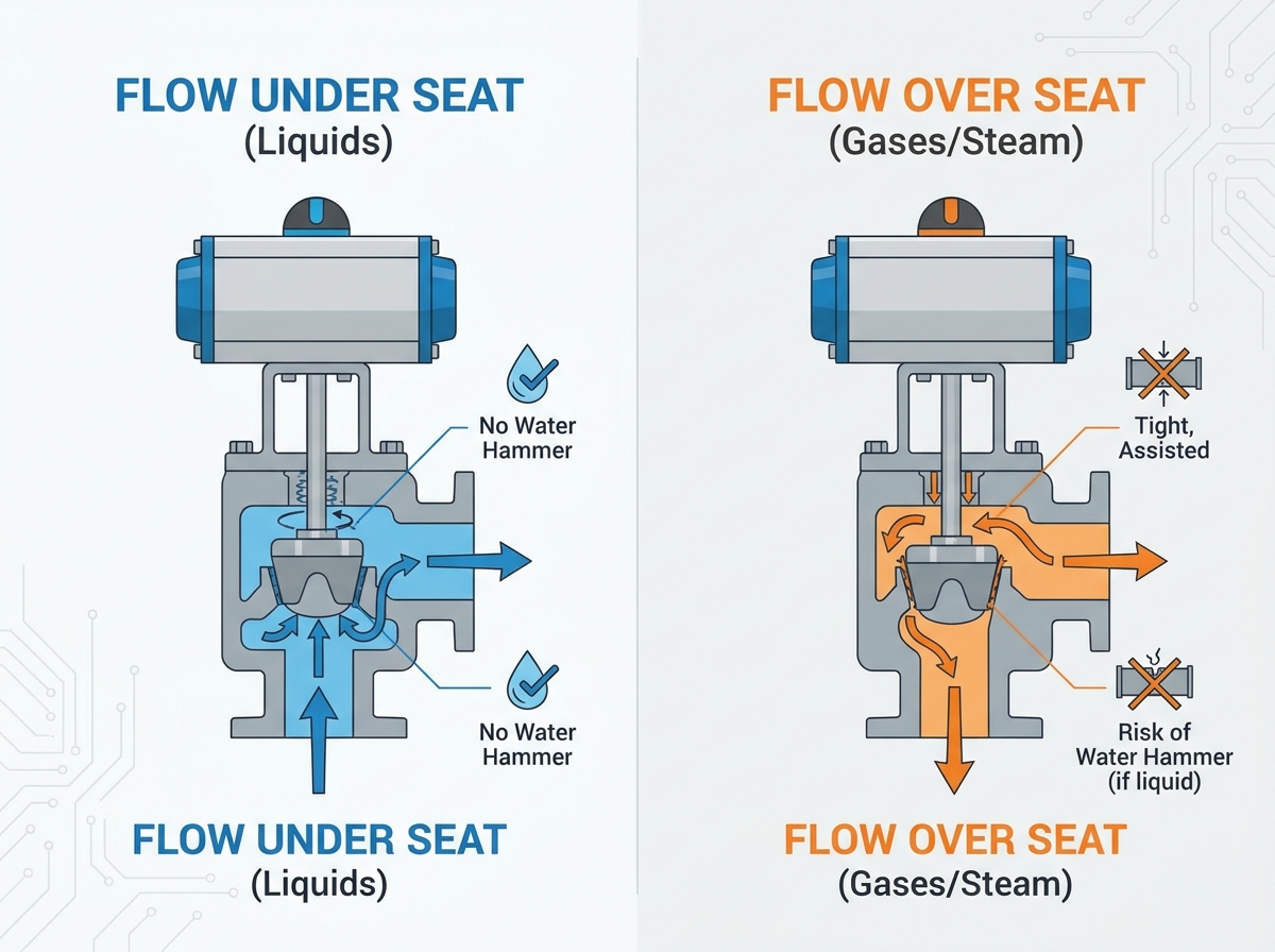
The physical orientation of the valve body relative to the incoming media dictates its performance. Because of the unique Y-body shape, fluid can enter from two different ports relative to the internal plug. Understanding angle seat valve flow direction prevents catastrophic piping damage.
In this configuration, the media pushes up against the bottom of the closed seal. This setup is mandatory for incompressible liquids. This includes water, sanitary fluids, and viscous industrial media.
The primary benefit involves fluid resistance. As the actuator forces the valve closed against the oncoming flow, the fluid's physical resistance naturally slows the closing speed. This dampening effect prevents hydraulic shock, known as water hammer. Water hammer can shatter pipes, rupture welds, and destroy expensive instrumentation.
However, this setup comes with a trade-off. It requires higher pilot air pressure. The actuator must exert enough downward force to overcome both the internal spring tension and the upward fluid pressure.
Here, the media enters above the seal, pushing down on it. This configuration works best for compressible media. You use this primarily for steam, compressed gases, and instrumentation air.
The primary benefit is seal integrity. The line fluid pressure actually assists the actuator. It pushes the valve closed, providing an exceptionally tight seal. Because the fluid does the heavy lifting, you can utilize a smaller, more cost-effective actuator.
You must observe one critical risk consideration. Never use over-seat flow for incompressible liquids unless the system is specifically engineered for it. The sudden closing force acts instantly. It slams the valve shut and causes highly destructive water hammer.
Flow Direction Comparison Summary
| Configuration | Media Type | Primary Benefit | Water Hammer Risk |
|---|---|---|---|
| Flow Under Seat | Liquids, Viscous Fluids | Anti-water hammer, smooth closure | Very Low |
| Flow Over Seat | Steam, Gases, Air | Superior tight shut-off, smaller actuator | High (if used with liquids) |
Proper sizing prevents operational failures. Engineers must calculate the exact mathematical relationship between the main line fluid pressure and the pneumatic pilot pressure. We refer to this relationship as Delta P (pressure differential).
The system pressure actively fights the actuator. If you run a high-pressure liquid line, your pilot air must supply sufficient counter-force. Actuator sizing logic plays a crucial role here. If you select an undersized actuator, it will fail to open fully in high-pressure lines. Worse, it may fail to close tightly against high flow, causing dangerous leaks. Conversely, oversized actuators introduce their own problems. They increase compressed air consumption unnecessarily. They also snap the valve shut too aggressively. This causes excessively harsh cycling and premature mechanical wear.
You must evaluate specific media properties during the sizing phase. High-viscosity media alter internal friction parameters. They require more force to cut through the fluid stream. Extreme temperatures also change the equation. For example, SIP (Sterilization in Place) or CIP (Clean in Place) processes in sanitary applications expose the valve to extreme thermal cycling. These environments require specific high-temperature PTFE seals. Heat expansion can increase internal friction. You must adjust your pressure calculations accordingly to ensure the actuator maintains smooth operation at peak temperatures.
Successful long-term operation relies heavily on how you install the unit. Proper pneumatic angle seat valve installation prevents early breakdowns and minimizes maintenance downtime. Follow a rigid, step-by-step approach.
Even perfectly specified valves experience occasional issues. A structured troubleshooting methodology helps operators identify root causes quickly. Here is how you address the most common failures.
Sometimes the valve chatters or only opens partially. This severely restricts your flow rate.
Passing occurs when fluid continues to trickle through a supposedly closed valve.
Media leaking out from the top of the valve body indicates a packing failure.
Angle seat valves provide unmatched flow rates and exceptional longevity for demanding applications. However, this reliability requires their fail-safe mode and flow direction to fundamentally align with the media phase and safety requirements. Installing the valve over the seat for gases, and under the seat for liquids, prevents critical pipe damage. Adhering to strict sizing and air quality standards eliminates most common operational failures.
Before purchasing your next valve, take action. Document your specific media type, maximum line pressure, and available pilot air pressure. Record your temperature extremes. Provide these exact metrics when requesting final sizing validation from your valve manufacturer or distribution partner. Proper documentation upfront guarantees a safe, durable, and highly efficient installation.
A: While physically possible, doing so alters the actuator force requirements drastically. It also risks inducing severe water hammer if incompressible liquids are suddenly routed over the seat. Always consult the manufacturer's specific pressure charts before reversing the piping direction.
A: This is a classic symptom of routing liquid "over the seat." The fluid dynamics pull the internal plug shut rapidly, causing a violent closure. Re-pipe the valve for "flow under seat" to naturally dampen the closure speed.
A: It varies depending on actuator size, line pressure, and spring tension. Typically, it falls between 40 to 90 PSI (3 to 6 bar). Always cross-reference the specific valve model’s pneumatic control graph for precise requirements.
A: Yes, they function well in vacuum environments. However, specific PTFE seals and inverted flow direction routing are often required. This setup maintains the internal vacuum seal without drawing ambient air through the upper packing gland.